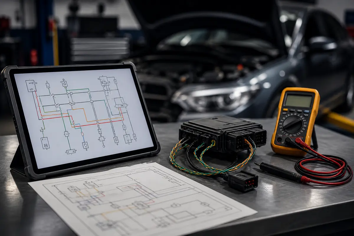
Automotive electrical diagrams are like maps guiding technicians through understanding complex systems. However, accurately interpreting these diagrams is not straightforward. With the rise of multiplexing and connections like CAN-Bus High Low, grasping the basics and applications of these systems is crucial to avoid common errors and ensure efficient diagnostics. In this guide, we will explore how to decipher these diagrams and the essential role they play in the operation of modern vehicles.
Basics of Automotive Electrical Diagrams
Electrical diagrams are visual representations depicting the interconnection of electronic and electrical components within a vehicle. The symbolism used can vary, but understanding the basic meaning of each symbol is key to interpretation. Components such as fuses, relays, and connectors have distinct representations, each indicating their function and connection. Moreover, it’s important to consider the type of current flowing through the systems: direct current (DC) or alternating current (AC), as this impacts the design of the electrical system. This foundation will enable you to move forward with the analysis of multiplexed systems such as CAN-Bus.
Breaking Down the CAN-Bus System
The Controller Area Network (CAN) is a communication protocol designed to facilitate data transfer between various control modules using a single pair of wires. The system operates through two main lines: CAN High and CAN Low, each transmitting signals differentially, enhancing robustness against interference. Multiplexing allows multiple components to communicate without requiring additional wiring, optimizing weight and space in the vehicle. For a technician, understanding how these channels are mapped in diagrams is critical for diagnosing issues, as any failure in these connections can lead to malfunction of the entire system.
Practical Guide for Diagram Interpretation
To effectively interpret an automotive electrical diagram, follow these steps: first, get familiar with the symbols used. Often, symbol catalogs can be found in the vehicle’s manual. Next, identify the power source and trace the current flow to the specific component you wish to analyze. Establish connections between components and verify if they correspond with the descriptions in the diagram. Finally, pay special attention to the CAN-Bus lines, recognizing which modules are involved and how they communicate with each other. This process will not only enhance your skills but will also save you time diagnosing problems.
Common Mistakes and Best Practices
One of the most common mistakes in interpreting electrical diagrams is the negligence of following the current flow accurately. It is crucial to trace this path precisely, as a cut or error in connection can lead to incorrect diagnoses. Additionally, distinguishing between different types of lines (e.g., power lines vs. data signals) is paramount. A good practice is to conduct cross-checks frequently and document your findings and diagnoses. Don’t underestimate the importance of software diagnostics updates, as modern vehicles heavily rely on this kind of technology. Stay updated with the latest tools and practices in automotive fields.
Conclusion
Interpreting automotive electrical diagrams and CAN-Bus lines may seem challenging, but with the right approach and practice, it becomes an invaluable skill. Remember, the key lies in understanding each component and its function within the system. Continually train yourself on diagnostic tools and stay informed about emerging technologies. As a practical tip, start applying this guide in real-world cases and keep a record of your learnings for continuous development in your career.
Keywords: diagrama lectrico automotriz, CAN Bus High Low, multiplexado, arnes
Views: 10